Silicon Microarray Spotting Pins : PETC Pins
Please contact us for further information about how to purchase or license these technologies. OEM inquiries welcome.


Pins and Printhead
Information


Ordering Information

Use and Maintenance

User Data and FAQs

Home

Partially Etched Through Channel (PETC) Pins

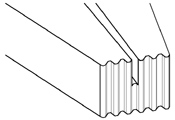
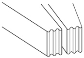
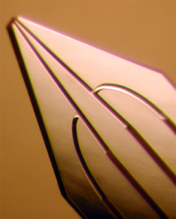
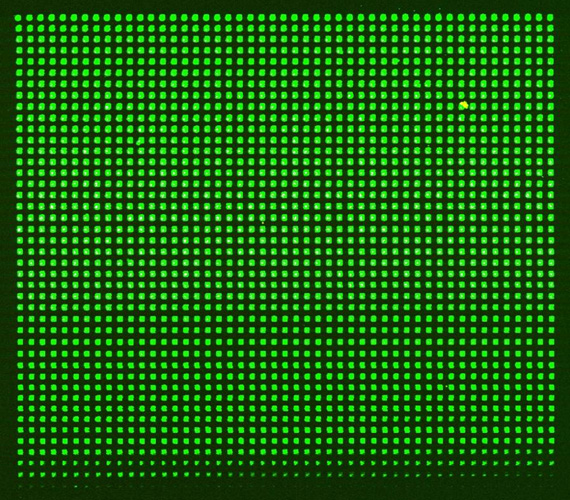
Parallel is very pleased to announce the introduction of silicon pins with Partially Etched Through Channel (PETC), the next generation Silicon Microarray™ micromachined silicon printing tools, to increase the ease and accuracy of printing your DNA, protein or other microarrays. Unlike the classic Si pins, whose internal channels are open to the outer surfaces on both sides of the pin shaft, PETCs contain channels that are open to only one of the two outer surfaces (Fig 1, 2 and 3). These new ultra-precise set of silicon printing tools can deliver up to four times as many spots as our classic pins with a %CV for spot-to-spot uniformity of only 2%. The greatly improved performance derives from the ultraprecise silicon micromachining techniques which can be used to sculpt miniscule pin tip features. The print fluid conduit connecting the reservoir and print tip does not pass all the way through the pin shaft but passes only part way through the shaft. This design functionally mimics a miniscule flow restrictor precisely metering the print fluid through the restriction to the substrate resulting in a more uniform delivered flow.


Fig. 1 Schematic representation of a PETC pin tip (left) and a classic pin tip (right).

Fig. 2 Photomicrographs and
schematic representations or print
tips with one, two, and four PETCs.

Fig. 3 Photomicrograph of a PETC pin tip region containing four channels connecting the reservoirs to the 75µm x 75µm pin tip.

Features, Advantages and Benefits of PETC Pins
The shape and dimensions of the pin tip features affect the size, number, shape and volume of the printed spots and thereby exert a pronounced effect on the size, uniformity, and the number of spots that can be printed per sample uptake. PETC pins offer several advantages over the classic pin designs, including improved control over the size and uniformity of printed samples through manipulation of dimensions and geometry of the channel that connect the pin reservoir and the tip surface. By altering the shape of the PETCs, pins can be engineered with larger internal volume capacity, greater mechanical strength, easier ability to be cleaned and decreased susceptibility to clogging. The result of these improvements is a printing tool with extremely precise metering of fluid dispensation with a mechanically strengthened print tip, which will allow , DNA or protein microarrays of improved spot quality and quantity to be produced at a lower cost. Table 1 lists some of the features and advantages that can be obtained using PETC pins.

Table1 Features, advantages and Benefits of the PETC pin designs

Pin feature
Advantages
PETCs Control amount of fluid delivered per spot by controlling the size and shape of the channels connecting the reservoirs and the print tips.
Closed reservoirs Slow evaporation rate of sample during printing leading to more uniform spots due to reduced effect of concentration change in the printing solution during the course of the printing.
Multiple channels a) Elimination of missing spots as plugging of one channel will not affect the fluid delivery of other channels; b) More uniform spots due to uniform delivery of fluid by many smaller channels as compared to one big channel
Multiple reservoirs Larger sample volume uptake; more number of deliverable spots per each uptake.
Print tip is one piece instead of two Stronger print tip will maintain original shape longer than open capillary pins thereby giving more uniform spots during a longer pin lifetime.

Printing Performance of PETC Pins
The performance of PETC pins was evaluated by printing DNA microarrays and comparing them to arrays printed with the classic, open capillary Si pins. For a given pin tip size and uptake volume, the PETC designs delivered smaller spots, larger number of spots, and greater spot-to-spot uniformity as compared to the open capillary pins. One of the factors that influence the spot size and reproducibility is the narrow width of the PETC as it exits the pin shaft onto the print tip, which acts analogously to a flow restrictor in that it mediates the flow between the reservoir and the print tip. The data in Figs. 4, 5 and 6 illustratethe dramatic effect on spot size induced by the size and shape of the channel as it exits onto the print tip. The smaller the PETC channel dimension as it enters the print tip, the smaller and more uniform are the spots that result. As shown in Fig. 5, the combination of four reservoirs and a m PETC can give as many as 2000 spots from a single source plate visit. Fig. 6 shows the plot which compares the spot size profile of the three arrays shown in Fig. 4.

Click on the images to see an enlarged view

Fig. 4 Scanned microarray images of Cy3 labeled 9-mers in 3x SSC printed from a single uptake volume using silicon pins having a tip size of 75x75µm with various channel. The spots are printed on a 180µm spot pitch and the width and depth of the channels near the pin tips are 15µm x 75µm (left), 10µm x 35µm (middle), and 2µm x 75µm (right). As can be seen from the above images the spot uniformity and number of spots increases with the decrease in channel size.

Fig. 5 Scanned image of an array of ~2000 spots prined from a single uptake volume. Spot pitch: 180µm, tip size:75µm x 75µm.


Fig. 6 A plot of spot size and coefficient of variance for groups of first 100, 200, 300 and 400
spots printed with three different types of pins all of which have 75
µm x 75µm print tips

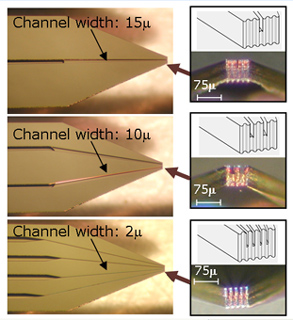
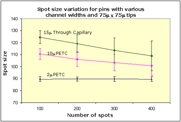
It is interesting to note that there is a strong effect from the size of the channel connecting the reservoir on the deposited spot size. A commonly held misconception is that somehow during microcontact printing, the printing fluid deposited onto the substrate from the pin's print tip which is parallel to the substrate. A cursory analysis shows that there is not nearly enough fluid on the print tip surface to account for the deposited drop volume. For example, even if the film of printing fluid adhering to the surface of the print tip that is parallel to the substrate is 1µm thick and the print tip is 75µm x 75µm , there are only about 5 pL of printing fluid on the print tip. However, based on the number of spots obtained per dip of the pin, the deposited spot volume of a printing fluid like random cy3-labeled 9-mers in 3X SSC on amine coated glass slides is closer to 200-300 pL. Therefore, the printing fluid on the pin's print tip is only a few percent of the total deposited drop volume.

Since there is not nearly enough fluid adhering to the print tip to account for the observed spot volume, the deposited volume must originate from within the fluid filled channel connecting the print tip. Furthermore, most of the deposited spot volume is removed from the channel as the pin is drawn away from the substrate. In other words, the wettable substrate surface draws the fluid from the pin shaft as the pin is withdrawn away from the surface. Further support for this mechanism is provided by study the printing behavior of a pin in which there is a thin (<10µm ) film of silicon directly on the print tip and parallel to the surface of the substrate (i.e. connecting the tips of the two prongs of the split pin shaft together). Even though photomicrographs show the entire print tip to be covered with a thin film of water, this type of pin will not print multiple spots - presumably due to the inability of the substrate to remove the printing fluid from the channel because of the silicon separator between the channel and substrate.The improved design manifests itself in more spots printed per source plate visit and a substantially higher pin to pin uniformity. Table 2 compares the printing parameters and spot size uniformity for two different PETC pin tips to a classic pin tip with the same tip size and uptake volume.

Table 2 Comparison of arrays printed with Si Pins having 75µm x 75µm tip size
(Arrays are printed on one slide in test print mode)

Channel dimensions near pin tip
(channel width x channel depth)
PETC
2 µm x 35µm
PETC
10 µm x 35µm
Classic channels
15 µm x 75µm
Average spot diameter
90µm
100µm
110µm
% CV (for the first 250 spots)
2%
5%
6%
Total number of spots per one dip
700-800
600-700
400-500
Volumetric uptake
~0.125µL
~0.125µL
~0.125µL


Copyright © 2000-2007 Parallel Synthesis Technologies, Inc. All Rights Reserved.
3054 Lawrence Expy. Santa Clara, CA 95051
info@parallel-synthesis.com, Phone:(408) 749-8318 Fax:(408) 749-8318